
Common Gate Types in Injection Mold and Engineering Judgment
In injection mold, the gate is far more than a point where melt enters the cavity. It sets the terms for filling, packing, cosmetic quality, and demolding stability. Many defects that appear on the surface — sink marks, weld lines, short shots, flow marks — do not originate at the surface at all. Their root cause is usually a mismatch between gate type, gate size or gate location, and the part’s actual geometry.
Selecting a gate should start with the part itself: structure, material, wall thickness, flow length, and cosmetic requirements. Production cycle time and tooling cost come next. This sequence — part first, cost second — is the more reliable way to evaluate plastic injection mold tooling design.
1. Sprue Gate
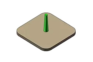
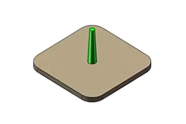
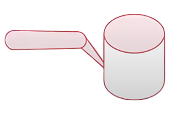
A sprue gate, also called a direct gate, feeds melt from the main runner straight into the cavity. Flow resistance is low and fill speed is fast, which makes it a strong choice whenever filling capability is the priority. It is most common on thick-wall parts, large parts, single-cavity molds, or functional components where the gate area falls outside the visible cosmetic surface.
Application Conditions
Direct gates generally suit materials with moderate-to-good flowability and parts with thicker walls, typically 2.5mm or above. If the parts primary cosmetic surface sits near the gate, or any visible gate mark is unacceptable, this is not the first option to reach for.
Common Defects
The typical problem with a direct gate is not insufficient fill — it is fill that arrives too fast and packs unevenly. If sink marks appear near the gate, first check whether pack time actually covers the freeze-off of the thick-wall region before concluding the gate itself is oversized and causing slow local cooling and concentrated shrinkage.
2. Pin-Point Gate
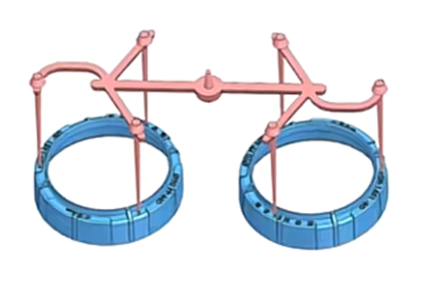
A pin-point gate, typically paired with a three-plate mold, uses a small gate diameter that separates automatically on mold opening. It suits parts with demanding cosmetic requirements. Its core value is a minimal gate mark, not higher fill capacity.
Application Conditions
This gate works best with good-flow materials, thinner walls, and shorter flow lengths — commonly 0.8mm to 3mm wall thickness. For high-appearance plastic injection tooling projects, if the part is large or the flow path is long, a pin gate can easily become a filling bottleneck.
Common Defects
Typical issues include short shots, burn marks, and inconsistent gate break-off. When a short shot appears, the first question is whether flow is being restricted at the gate or melt is cooling too quickly there — not whether injection pressure needs to go up. Burn marks call for checking both the injection speed profile and venting together, not either one in isolation.
3. Edge Gate
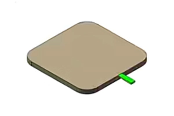
An edge gate also called side gate, it sits on the parting line and feeds the part from its edge. It is one of the most widely used gate types, structurally simple and straightforward to machine, and it suits most conventional parts.
Application Conditions
Side gates work well for wall thicknesses around 1.5mm to 4mm, medium-sized parts, and cosmetic surfaces that can tolerate a small gate mark. For projects seeking injection mold tooling in China, this gate type often offers the best balance among cost, manufacturability, and production stability.
Common Defects
If a weld line consistently appears in the same location, the gate position is the first thing to question — not insufficient pressure. Flow marks concentrated near the gate usually trace back to fill direction, gate size, or injection speed. If a short shot occurs at the far end of the part instead, check the flow path and gate size first.
4. Tunnel Gate
A tunnel gate also called submarine gate, it enters the cavity from below the parting line and severs automatically as the injection mold open. It suits production programs that need automatic degating and a hidden gate location.
Application Conditions
Tunnel gates generally suit wall thicknesses around 1.2mm to 3.5mm, small-to-medium parts, and materials with reasonable toughness. Materials that are too brittle, or flow paths that run too long, call for caution. The figures above are starting points only — final values should be refined against material behavior, break-off geometry, and trial-mold results.
Common Defects
Stringing or a rough break-off points first to the tunnel angle and gate length, then to whether mold-opening stroke is sufficient. A whitened or heavily marked break-off area typically indicates stress concentration at the break point.
Frequently Asked Questions
Q1: Is a smaller gate always better?
No. An undersized gate restricts flow and leads to short shots or burning. Gate size needs to match the material and flow length, not be minimized on its own.
Q2: Why does gate performance change when the material changes?
Different materials flow and shrink differently, which directly affects how the gate fills and how cleanly it breaks off.
Q3: When is changing the gate design actually necessary?
When a defect recurs at the same location and process adjustments cannot eliminate it, the gate design itself — not the process window — is likely the issue.
Q4: Why is a side gate sometimes unstable?
Because its performance is sensitive to gate position, flow path, and speed control. It is not a universal fit for every part structure.
Q5: Why is tunnel gate tuning so difficult?
Because its break-off behavior depends simultaneously on structural parameters, material properties, and the mold-opening motion.
Q6: What is the single most important gate decision early in a project?
Confirming the cosmetic requirements, whether automatic degating is needed, and whether the material and wall thickness actually support the gate type under consideration.
Q7: Can typical reference dimensions be applied directly?
No. Every reference figure is a starting point. Final dimensions must be validated through trial molding or flow analysis.