
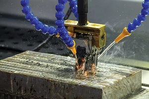
Engineering Characteristics of EDM in Injection Mold Cavity and Core
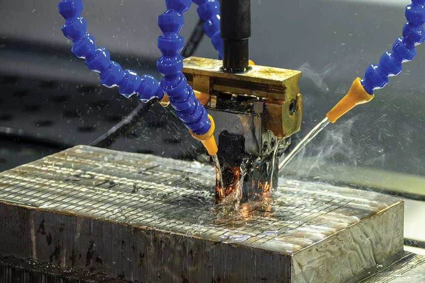
Electrical Discharge Machining (EDM) is the second major critical operation in plastic injection mold manufacturing after CNC machining. Many engineers assume that CNC alone can achieve final mold dimensions, but EDM is essential for small internal corner radii, deep ribs, and complex textures that may be difficult or impractical to produce with conventional CNC milling tools.
When EDM produces dimensional errors or surface defects, the first suspect should be electrode accuracy and fixturing, rather than adjusting discharge parameters directly. This judgment approach forms part of PTMS’s mold manufacturing workflow in China. More information about the company’s equipment and engineering capabilities is available on the China manufacturer page. PTMS uses the highest quality raw materials and follows a perfect precision tooling process for high precision injection mold components. The final dimensions and radii depend on electrode accuracy, EDM stability, inspection control, and appropriate process planning.
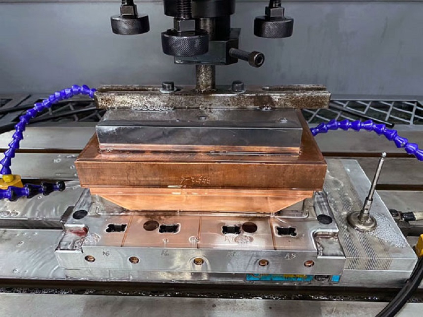
EDM Process: From Electrode to Final Cavity and Core
After CNC semi-finishing leaves stock on cavity and core surfaces, EDM removes the remaining material from selected cavity and core features to achieve the specified dimensions, radii, and surface condition.
Electrode Material Selection
Copper Electrodes:
- Application: Suitable where electrode geometry and dimensional control are important
- Surface finish: Capable of fine finish suitable for many different plastic injection mold applications
- Wear characteristics: Electrode wear should be considered in electrode design. In industry practice, copper electrode wear is typically compensated at 1:5 to 1:10 ratio depending on the machining stage and material.
- Best for: Fine details, small ribs, and controlled finishing operations
Graphite Electrodes:
- Application: Suitable for electrode designs involving larger material removal or complex shapes
- Surface finish: Standard finish suitable for many applications
- Wear characteristics: Different wear behavior compared to copper, requiring appropriate compensation
- Best for: Larger cavity areas and applications where the specified finish permits its use
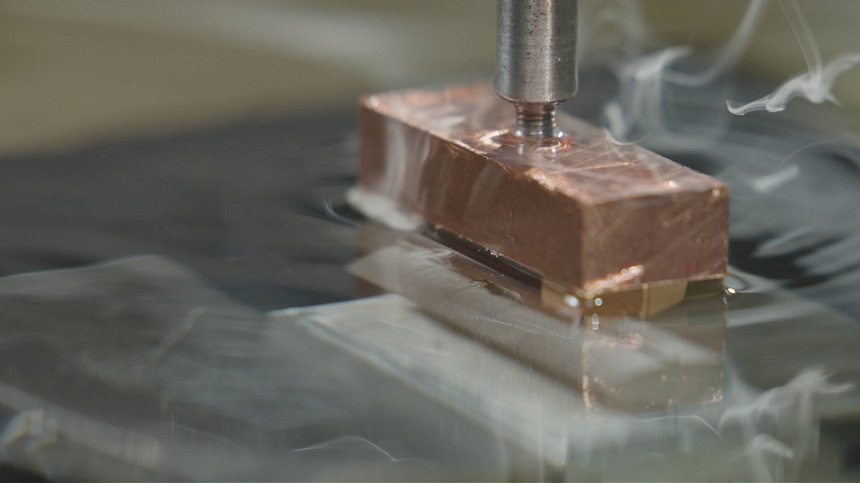
Machining Strategy for Precision EDM
Depending on the cavity geometry, electrode design, and required surface finish, EDM may use separate electrodes for roughing and finishing. The final electrode selection and machining sequence should be determined from the injection mold design and inspection requirements.
CNC establishes the basic cavity and core geometry, while EDM uses the finished copper electrode to refine the final cavity dimensions, corner transitions, and radii. Wire cutting then controls the profiles, locations, and fit of suitable through-features.
Advantages of EDM for Plastic Injection Mold Making
- Small internal corner radii and sharp details that may be difficult or impractical to produce with conventional CNC milling tools
- Deep cavities and ribs with high depth-to-width ratios
- Complex textures directly machined into cavity
- Machining of hardened conductive materials with limited mechanical cutting force
- Electrode wear can be considered and compensated for during electrode design and process planning
- Limited mechanical cutting force—reduces the risk of workpiece deflection and vibration associated with conventional milling
Common Defects and Solutions
| Defect | Possible Cause | Priority Check |
| Electrode wear | Excessive current, unsuitable electrode material, or long machining time | Verify electrode material selection and machining parameters |
| Taper on deep cavities | Uneven spark gap, servo instability, electrode misalignment, or insufficient flushing | Inspect servo response, spark-gap stability, flushing condition, and electrode alignment first |
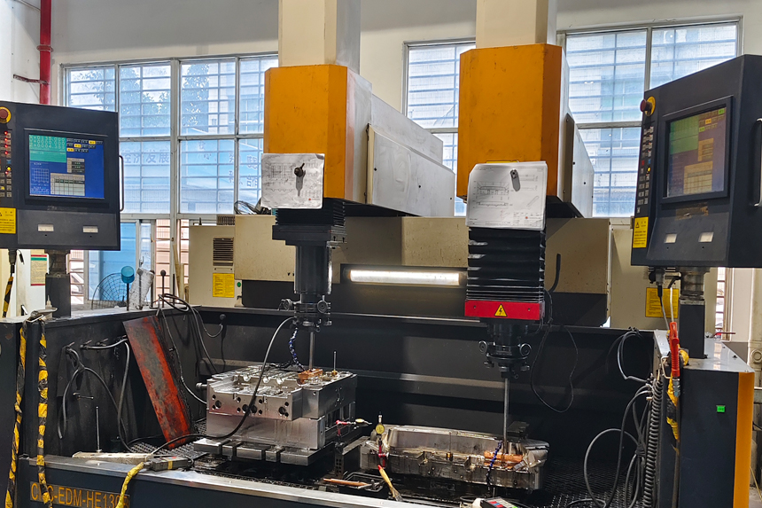
Dimensional Errors and Surface Defects Solution
When EDM produces dimensional errors or surface defects, the first suspect should be electrode accuracy and fixturing, rather than adjusting discharge parameters directly.
Priority Inspection Sequence:
- Electrode dimensional accuracy should be checked first—CNC-machined electrodes must be verified before EDM.
- Electrode fixturing and alignment should be prioritized before blaming machine accuracy—misalignment causes taper, uneven wear, and dimensional drift.
- Dielectric fluid condition should be verified if surface finish degrades—contaminated fluid causes arcing, pitting, and inconsistent material removal.
- Spark gap consistency should be inspected if tolerance is not achieved—servo control must maintain stable gap for consistent machining. In industry practice, spark gap typically ranges from 0.01mm to 0.05mm depending on the machining stage and required surface finish.
If EDM provides limited improvement after these checks, then power supply stability, servo response time, and thermal compensation should be evaluated.
Application Conditions
EDM is suitable for final cavity and core finishing after CNC semi-finishing. For selected high precision features completed through the overall plastic injection tooling process, the common tolerance is +/-0.01mm and even +/-0.001mm, while other customized dimensions can be produced according to the drawing and inspection requirements.
For suitable through-features, such as ejector pin holes, lifter slots, and through-type insert openings, wire EDM may be selected when the geometry and access conditions allow the wire to pass through the workpiece. When evaluating a plastic injection mold maker in China, engineers should verify the supplier’s EDM equipment type, electrode machining capability, and inspection method for their specific mold geometry.