
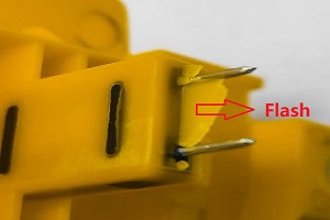
Flash in Plastic Injection Molded Parts: Causes and Solution
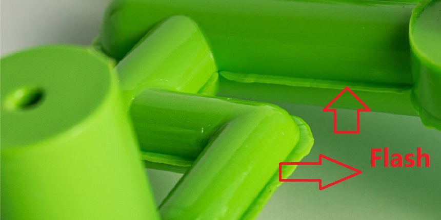
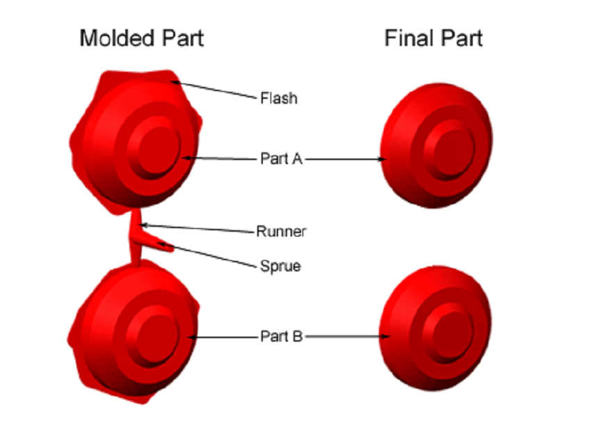
Flash is a thin, unwanted layer of plastic that escapes from the mold cavity and remains along the edge of a finished part. It may look minor at first, but excessive flash can affect cosmetic quality, create assembly interference, increase trimming work, and indicate that the mold or process is operating outside a stable condition.
In plastic injection molded parts, flash should be evaluated by its location and pattern before process settings are changed. A thin edge that appears repeatedly at one mold interface requires a different response from flash that appears more broadly around the parting line during production.
What Flash Looks Like?
Flash typically appears as a thin, uneven edge of material running along the parting line, gate area, or other mold interfaces. Sometimes it is only a hairline ridge; in more severe cases, it forms a visible plastic fin that can be felt with a fingernail or catch during assembly and packaging.
It tends to be more noticeable near corners, thin ribs, deep pockets, and other areas where mold sections are harder to seal completely under injection pressure.
Flash forming along a molded part’s parting line
Flash may appear as:
– A fine ridge following the parting line
– A thin plastic fin extending beyond the intended part edge
– Localized excess material around inserts, sliders, or shut-off areas
– A continuous or intermittent line around the perimeter of the part
Minor flash may be removed during post-processing, but trimming should not replace root-cause correction. If the mold continues to produce flash, the condition can worsen as mating surfaces wear or process variation increases.
Flash Acceptance Reference
The acceptable amount of flash should be defined by the part’s cosmetic requirements, assembly function, customer specification, and inspection standard.
A common general reference is to keep flash below 0.004 in (0.10mm). However, this is not a universal acceptance limit. Parts with tighter cosmetic, functional, or precision requirements may require a lower limit, while any flash that feels sharp, interferes with assembly, or affects sealing should be corrected regardless of thickness.
What is the reason for Flash Lines?
Flash lines visible along the edge of a finished part
Five main factors should be reviewed when flash lines appear.
1. Insufficient Clamping Force
Clamping force keeps the injection mold closed while cavity pressure rises during filling and packing. If the machine cannot provide enough force for the part’s projected area and the pressure being used, the mold halves can separate slightly during injection molding mass production.
Even a very small opening at the parting surface can allow molten plastic to escape and form flash.
This issue is more likely when:
– The mold is running close to the machine’s clamping-force limit
– The part has a large projected area
– The cavity pressure is high
– The machine setting does not match the actual molding condition
Insufficient clamping force may create flash around a large portion of the parting line rather than at only one small location.
2. Excessive Clearance at Mating Mold Surfaces
Flash can also occur when the mold cannot seal properly. Worn, damaged, misaligned, or poorly matched surfaces can leave gaps that allow melt to enter areas outside the intended cavity.
Common locations include:
– Parting surfaces
– Insert interfaces
– Slider contact areas
– Shut-off surfaces
– Mold edges subject to wear or damage
Proper venting also supports stable filling by allowing air to escape from the cavity. When venting is restricted, higher injection pressure may be required to fill the part, increasing cavity pressure and the tendency for the mold halves to separate.
At the same time, vent dimensions must remain controlled. A vent that is too deep, damaged, or unsuitable for the material may allow molten plastic to escape and create localized flash.
When flash consistently appears in the same area on every shot, local mold fit and vent condition should be examined carefully. A process adjustment may reduce the visible flash, but it may not eliminate the underlying gap or venting issue.
3. Injection Pressure or Packing Pressure is too High
Higher injection pressure can force melt into any available gap. In some cases, pressure has been increased to compensate for another issue, such as a short shot or difficult filling condition. This may fill the part more completely, but it can also push material through the parting line.
High packing pressure can create the same effect after filling. If the injection mold is already close to its sealing limit, excessive packing pressure may produce flash even when the initial fill stage appears stable.
Pressure should therefore be reduced only after confirming that the part can still fill properly. The target is not the lowest possible pressure, but the minimum pressure needed for stable filling and packing.
4. Melt Temperature is too High
Higher melt temperature lowers material viscosity and makes the melt flow more easily. This can help fill thin sections, but it also makes it easier for material to enter small gaps at the parting line or other mold interfaces.
If melt temperature has been raised to solve a separate filling issue, flash may appear as a side effect. Temperature should remain within the material’s recommended processing range and should be reviewed together with injection pressure, packing pressure, and mold condition.
5. High Material Flowability
Some materials or grades flow more easily than others. A highly flowable melt can enter smaller gaps, making mold fit, clamping force, and process control more critical.
This does not mean that a high-flow material will always produce flash. It means that the mold must maintain a reliable seal and the process must avoid unnecessary pressure or temperature increases.
What is the Solution for Flash Lines?
Mold Engineers
– Inspect the parting surface for wear, damage, contamination, or poor contact.
– Repair the parting surface when wear, damage, or poor mating creates a melt-escape path.
– Check slider, insert, and shut-off interfaces for localized gaps.
– Review venting geometry to ensure vent areas do not create an unintended path for melt escape.
– Confirm that mold alignment and closing conditions remain stable during injection molding production.
Process Engineers
– Increase clamping force when the machine setting is insufficient for the actual cavity-pressure condition.
– Reduce injection pressure to the minimum level needed for complete filling.
– Review packing pressure and avoid using excessive pressure to compensate for unrelated filling issues.
– Lower melt temperature within the material’s recommended processing range when excessive flowability contributes to flash.
– Change one process condition at a time during troubleshooting so the actual cause can be identified.
Part Designers
– Review shut-off areas and mold-closing features early in the design stage.
– Avoid part geometry that creates unnecessarily weak or difficult-to-seal shut-off conditions.
– Consider whether wall thickness, flow path, and gate location may require excessive cavity pressure during filling.
– Confirm that cosmetic edges and assembly interfaces can tolerate the selected parting-line location.

How to Solve the Problem Using an Engineering Approach?
The location of flash provides an important starting point for troubleshooting.
– Flash concentrated at the same location on every shot: Check the local parting surface, insert, slider, shut-off area, or mold fit first.
– Flash distributed more broadly along the parting line: Check clamping force, cavity pressure, and overall mold-closing stability.
– Flash appearing after pressure or temperature changes: Review injection pressure, packing pressure, and melt temperature before making mechanical changes.
– Flash that improves but does not disappear after process adjustment: Inspect the mold condition rather than continuing to adjust parameters.
The correct response is usually not to reduce temperature or pressure immediately. First determine whether the mold has a physical gap, whether clamping force is sufficient, or whether the process is creating unnecessary cavity pressure.
Frequently Asked Questions
Q1: Is flash the same as a burr?
In injection molding, flash is excess plastic that escapes from the cavity through a small gap in the mold. “Burr” is a broader manufacturing term for unwanted sharp or excess material. In practice, flash may be described as a plastic burr after molding.
Q2: How do I know whether clamping force is sufficient?
Clamping force should be evaluated against the part’s projected area and the cavity pressure required for filling and packing. If flash appears broadly along the parting line, especially on a larger part or multi-cavity mold, clamping capacity should be reviewed.
Q3: Can venting cause flash?
Yes. Venting is necessary for air removal, but an oversized, damaged, or unsuitable vent can create a path for molten plastic to escape. Venting should therefore be reviewed together with parting-surface condition and cavity pressure.
Q4: Which materials are more sensitive to flash?
Materials with higher flowability can enter smaller gaps more easily. For these materials, mold fit, clamping force, injection pressure, and melt temperature require closer control.
Q5: Can flash simply be trimmed off?
Minor flash can be trimmed when needed, but trimming does not correct the cause. Repeated flash increases secondary work and may indicate mold wear, poor fit, insufficient clamping force, or unstable process conditions.