Injection Mold Tooling Slider: Function, Characteristics, and Driving Methods
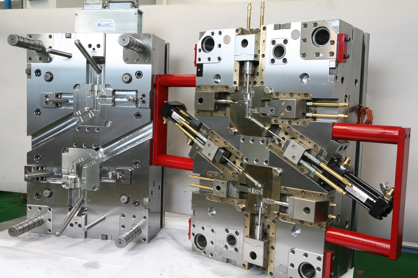
In injection mold design, the slider is one of the most common mechanisms for handling side holes, side recesses, undercuts, and complex lateral features. Its value lies not in whether the feature can be produced, but in whether it can achieve smooth demolding while maintaining mold strength, molding stability, and long-term maintainability.
Most slider problems don’t come from the mechanism itself being flawed — they come from the design stage failing to consider stroke, angle, tolerance, wear resistance, and driving method together. This gap later shows up as jamming, wear, flash, or unstable positioning during production. In plastic injection mold tooling, slider design is often the dividing line between structural complexity and mold reliability.
1. Function of the Slider
The core function of a slider is to complete lateral core-pulling during mold opening, resolving structures on the part that cannot be released by straight ejection alone.
It is mainly used for:
– Side holes
– Side recesses
– Undercuts
– Local features on complex external contours
Without a slider, many parts could only be produced by changing the structure, altering the parting line, or sacrificing design freedom to achieve demolding. The slider is therefore not just a mold mechanism — it is a bridge between product design and mold manufacturing.
Applicable Conditions
Sliders are suited to parts with lateral undercuts, small-to-medium core-pulling distances, and structures that cannot reasonably be resolved through inserts or parting line changes. They are common in structural parts, housings, and functional components with wall thicknesses of 1.5mm–4mm.
Engineering Judgment
If a part has a clear lateral feature but no core-pulling mechanism was planned for it, later stages usually force a reactive trade-off between demolding, appearance, and structure. If the undercut location is fixed and cannot be resolved through draft angle or parting line adjustment, a slider should be considered before any attempt to force a change in the part’s external shape.
Design Approach
Whether a slider is necessary isn’t a question of “can it be eliminated,” but “if eliminated, does the risk simply move elsewhere.” If reworking the structure would compromise appearance or strength while the core-pulling requirement clearly exists, the slider is usually the more reliable solution.
2. Characteristics of the Slider
Advantages
Sliders can resolve complex lateral structures, offer strong support for product design freedom, and suit most mid-to-high complexity molds. For parts that need to preserve an intact appearance surface, the slider is often the most direct demolding solution.
Disadvantages
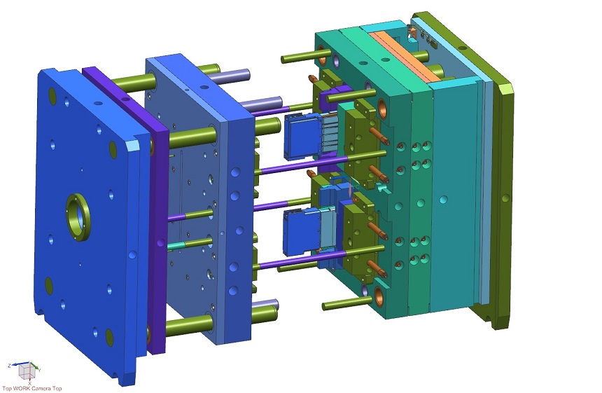
Slider structures are more complex, involve more components, and demand higher manufacturing and assembly precision. Wear, jamming, and positioning deviation occur more frequently, and long-term maintenance costs run higher than with simple straight-ejection structures.
Typical Risks
– Incomplete core-pulling can scratch or drag the part
– Excessive slider clearance easily produces flash
– Poorly matched driving angles are prone to jamming
– Guide surface wear over extended use directly affects precision and service life
Engineering Judgment
If a plastic injection tooling ran normally during initial trials but starts showing flash or positioning deviation after extended production, don’t look only at process parameters first — check the guide surfaces, locking blocks, and wear condition. If the problem was present from the start, the more likely cause is the slider’s dimensions, tolerances, or driving angle itself.
Design Approach
A slider isn’t something you install and expect to run indefinitely without attention — it has to maintain a balance between guiding, locking, wear resistance, and core-pulling action. In the early stage, what matters is whether the motion runs smoothly; over the long term, what matters is whether it stays stable after wear sets in. In real-world injection mold tooling in China projects, the final slider solution is rarely the theoretical optimum — it’s usually the most balanced outcome among cost, reliability, and manufacturing capability.
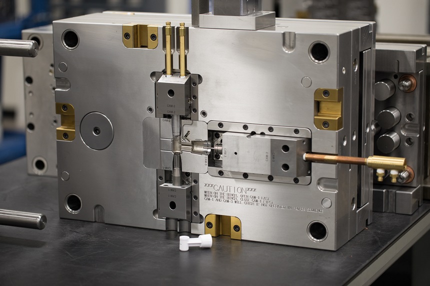
3. Main Driving Methods for Sliders
3.1 Angle Pin Drive
This is the most common slider driving method. It uses the inclined surface of an angle pin to convert the mold’s linear opening motion into lateral core-pulling.
Applicable Conditions
– Small-to-medium core-pulling strokes, typically 5mm–20mm
– Low core-pulling force
– Cost-sensitive projects
– Best suited to conventional parts with relatively stable wall thickness and shorter lateral core-pulling distances
Engineering Judgment
If slider motion isn’t smooth, check the angle pin’s angle and travel path first, then check the guide surface for uneven wear. If jamming occurs near the end of the core-pulling stroke, the cause is usually not “insufficient force” but a mismatch among angle, guiding, and locking that were never coordinated together.
Design Approach
The pin angle should not be too steep, or wear and lateral loading both increases. As stroke length grows, pin strength and guiding stability need to be checked in parallel. Locking and guiding must be designed as a matched pair — otherwise the mold can shift under molding pressure.
3.2 Hydraulic Drive
A hydraulic cylinder directly pushes the slider to complete core-pulling.
Applicable Conditions
– Longer core-pulling strokes, typically over 20mm
– Higher core-pulling force
– Projects requiring precise control of the core-pulling motion
– Better suited to large or complex sliders, or structures where angle pin driving is no longer economical
Engineering Judgment
If the core-pulling distance is long and mechanical driving is already near its practical limit, evaluate whether hydraulic driving better fits the structural requirement rather than continuing to scale up the angle pin. If motion is out of sync or repeat positioning is unstable, check the oil circuit, seals, and control system first — not just the slider body.
Design Approach
Hydraulic systems provide greater core-pulling force and better stroke control, but also mean higher cost and maintenance complexity. If field maintenance conditions are limited, a hydraulic solution should be evaluated in advance for leakage risk, synchronization, and serviceability.
3.3 Pneumatic Drive
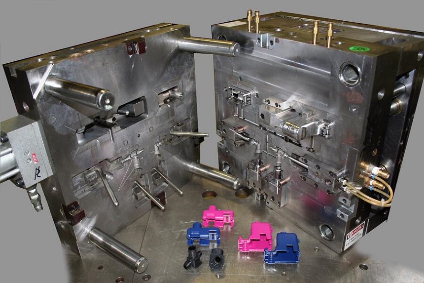
A pneumatic cylinder drives the slider motion.
Applicable Conditions
– Short strokes, typically under 10mm
– Light-load core-pulling
– Products where system simplicity matters
– Best suited to structurally simple, low-frequency, light-load mechanisms
Engineering Judgment
If the slider load is small but structural simplicity is a priority, pneumatic driving can be a reasonable option. If there is noticeable lateral loading or core-pulling resistance, pneumatic driving usually isn’t the first choice.
Design Approach
Pneumatic solutions respond quickly and cost less, but the driving force is limited — stability and repeat positioning accuracy are generally lower than hydraulic systems. It’s suited to light-load mechanisms, not to high-force or high-stability requirements.
A slider isn’t “working” simply because it moves — what matters more is whether it returns to position accurately and locks stably at mold closing. If locking isn’t stable, injection pressure can shift the slider during molding, producing flash or dimensional deviation.
FAQ: Common Slider Questions
Q1: What problem does a slider primarily solve?
Sliders primarily resolve structures — side holes, side recesses, undercuts — that cannot be released by direct ejection.
Q2: Why is angle pin driving the most common method?
Because it’s structurally simple, low-cost, and easy to maintain, making it suitable for most conventional molds.
Q3: Is a hydraulic slider always better than an angle pin?
Not necessarily. Hydraulic driving suits long strokes, high core-pulling force, and high control requirements, but comes with higher cost and maintenance demands.
Q4: Why do sliders tend to produce flash?
Usually because locking isn’t fully engaged, clearance is excessive, or molding pressure pushes the slider open.
Q5: What’s most often overlooked in slider design?
Stroke margin, guiding precision, locking structure, and long-term stability after wear — these four are the most commonly overlooked.
Q6: How do you tell if slider jamming is a design issue or a manufacturing issue?
If jamming persists after reworking assembly and fitting, it’s most likely a design issue. If it improves noticeably after fitting adjustments, it’s usually a manufacturing or assembly deviation.
Q7: Why is a slider mechanism harder to maintain than a standard structure?
Because it adds core-pulling motion, guide surfaces, locking surfaces, and driving components — wear in any one of these affects overall stability.
Q8: A mold starts jamming after extended production — what should be checked first?
Check the guide surfaces and wear plates first, then the locking blocks for uneven wear. Don’t jump to adjusting process para